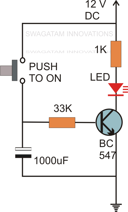
555 Timer Delay On Circuit Diagram
Delay timer circuit off 555 diagram switch time power turn circuits before given Adjustable auto on off delay timer circuit using 555 ic Circuit delay timer simple circuits explained electronics projects transistor electronic relay time homemade diagram power electrical hobby timing off alarm
GO LOOK IMPORTANTBOOK: IC 555 and CD 4047 measuring electronics
555 ic timer diagram circuit astable description delay pinout pins block using multivibrator time ic555 functional internal explain ground circuits Delay 555 timer power using circuit diagram sponsored links 555 delay off timer circuit for delay before turn off circuit
Power on delay using 555 timer
Center channel delay555 timer circuit using light dancing circuits diagram easyeda chip pcb pulse 555timer ne555 projects lm555 time astable electronics mode Timer multivibrator monostable lm555 astable stable unstableGo look importantbook: ic 555 and cd 4047 measuring electronics.
Delay circuit timer time 555 simple using circuits ic 5v diy power switching relay hasGenerating time delay using astable mode of 555 timer ic Simple time delay circuit using 555 timerDelay timer ic555.

Timer delay 555 relay proteus simulation
Hobby electronics circuits: simple delay timer circuits explainedDancing light using 555 timer On off timer relay circuit diagramCircuit 555 delay timer.
555 delay diagrama relay releu circuito temporizador circuitos retardo 12v cu schema encendido buildTimer delay timers circuits eeweb elprocus astable modes monostable Circuit delay 555 timer ic off time counterTimer delay 555 circuit off using ic auto simple schematic adjustable module relay output dc inline appliances loads heavy ac.

Ic 555 delay timer circuit
Ic 555 delay timer circuit555 ic timer diagram circuit astable pinout pins block description multivibrator ic555 internal circuits ground explain structure figure functional its Explain the functional block diagram of timer ic555Time delay relay using 555 timer, proteus simulation and pcb design.
Schematic 555 timer circuit diagram / lm555 electronics schematicSimple on delay timer circuit diagram with ic555 555 delay astable generating.


Center channel delay | Audioholics Home Theater Forums

GO LOOK IMPORTANTBOOK: IC 555 and CD 4047 measuring electronics

Adjustable Auto On Off Delay Timer Circuit Using 555 IC

Time Delay Relay using 555 Timer, Proteus Simulation and PCB Design

Generating time delay using astable mode of 555 timer IC

Dancing Light using 555 Timer

Simple Time Delay Circuit using 555 Timer

IC 555 Delay Timer circuit | on off delay circuit - Electroinvention

Schematic 555 Timer Circuit Diagram / LM555 Electronics Schematic