Timing Diagram Of 8:1 Mux
Timing diagram of 2:1 mux using cmos logic in dsch2 (pdf) cmos design of 2:1 multiplexer using complementary pass Latch-mux implementation of detff [1], and illustration of the timing
Latch-MUX implementation of DETFF [1], and illustration of the timing
Construct 16-to-1 line multiplexer with two 8-to-1 line multiplexers Using mux timing cmos multiplexer cpl diagram complementary transistor logic pass layout Asynchronous timing electronics
Multiplexer ic logic combinational circuits table truth tutorial electronics below figure
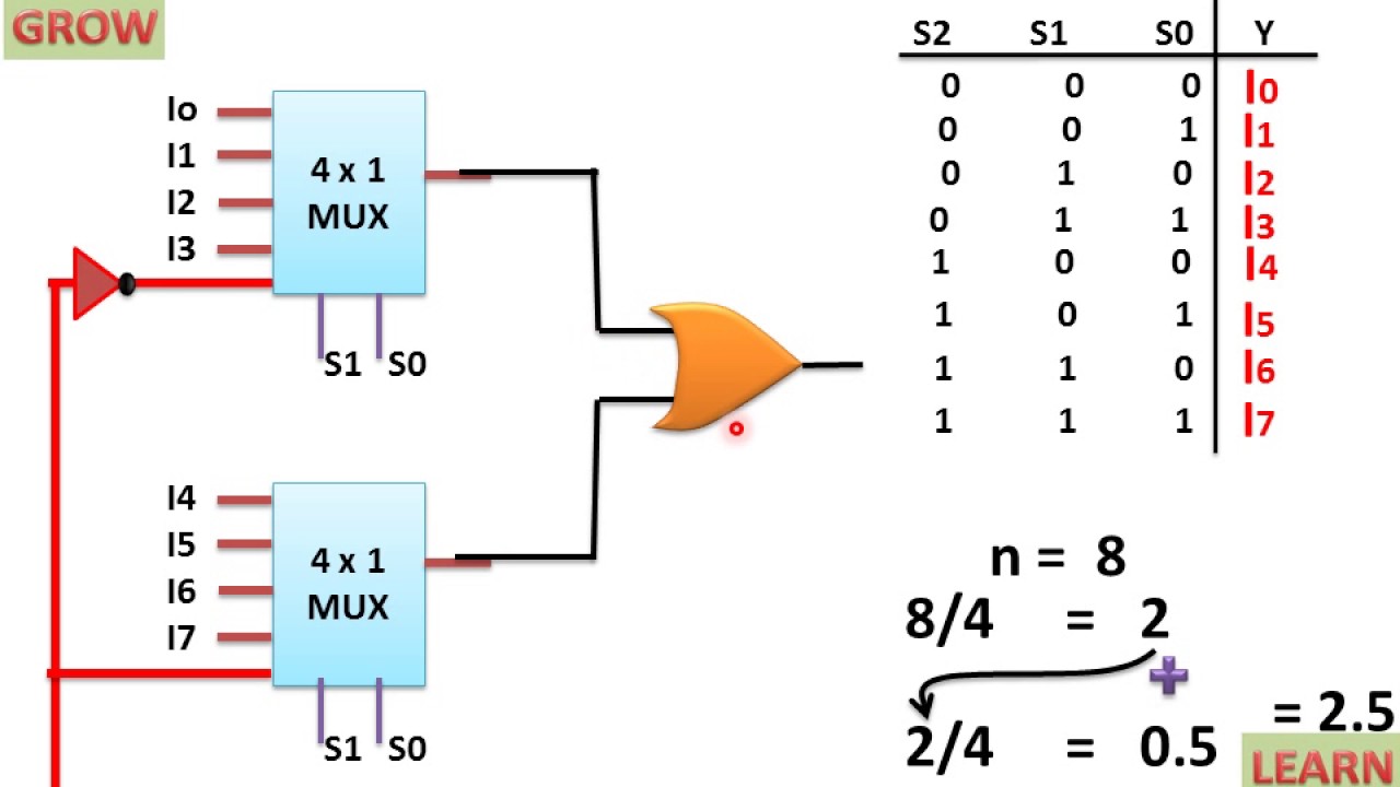
Timing diagram of asynchronous counter8x1 mux logic diagram : using 8 1 multiplexers to implement logical Implementation latch mux timingCmos mux timing logic.
Multiplexer mux implement plc truth logic sanfoundry gatesFigure 3 from power optimization of 8:1 mux using transmission gate Plc program to implement 8:1 multiplexerMux tgl logic optimization gating.

8x1 mux multiplexer 4x1 logic implementation implement multiplexers logical 2x1
Mux 16 two construct multiplexer diagram block line multiplexers constructed dec2005 suitable assumptions 5m makes any if .
.


timing diagram of asynchronous counter - Electronics Coach

Multiplexer | Electronics Tutorial

PLC Program to Implement 8:1 Multiplexer - Sanfoundry
![Latch-MUX implementation of DETFF [1], and illustration of the timing](https://i2.wp.com/www.researchgate.net/profile/Keisuke-Inoue/publication/270457537/figure/fig1/AS:392236891164688@1470527970963/Latch-MUX-implementation-of-DETFF-1-and-illustration-of-the-timing-diagram-where_Q320.jpg)
Latch-MUX implementation of DETFF [1], and illustration of the timing

Construct 16-to-1 line multiplexer with two 8-to-1 line multiplexers

Timing Diagram of 2:1 MUX using CMOS Logic in DSCH2 | Download
8X1 Mux Logic Diagram : Using 8 1 Multiplexers To Implement Logical